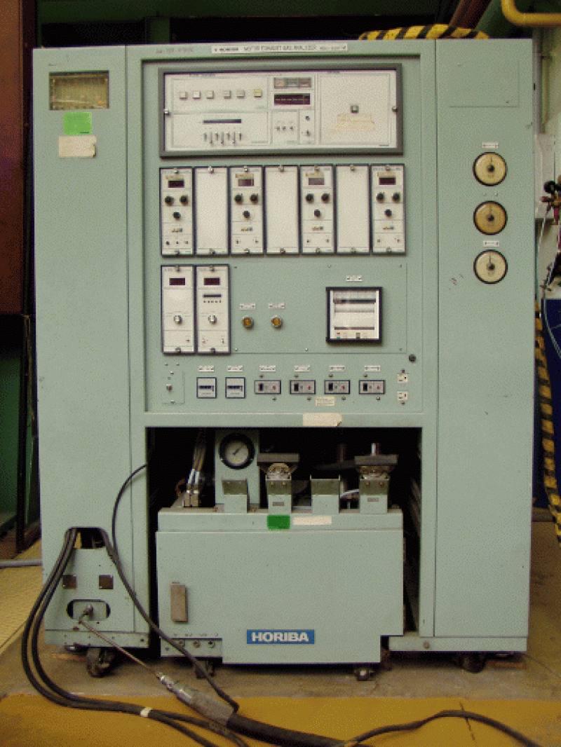
HORIBA MEXA-8120 F emission analyser system

In its current configuration, the system is equipped with 4 channels for measuring CO, CO2THC and NO/NOx emissions. The type of each channel:
CO analyser: AIA-23 (HORIBA),
measurement principle: NDIR (non-dispersive infrared),
Measuring ranges: 0-0,1 and 0-0,5 V/V %
CO2 analyser: AIA-23 (HORIBA),
measurement principle: NDIR (non-dispersive infrared),
measuring ranges: 0-8 and 0-16 V/V %
THC analyser: FIA-22 (HORIBA),
measuring principle: H FID (heated flame ionisation),
measuring ranges: 0-10, 0-20, 0-50, 0-100, 0-200, 0-500, 0-1000, 0-2000 and 0-5000 ppm
NO/NOx analyser: CLA-53
measuring principle: H CLD (chemiluminescence),
measuring ranges: 0-10, 0-20, 0-50, 0-100, 0-200, 0-500, 0-1000, 0-2000 and 0-5000 ppm
Main parameters:
Sample flow rate: 15 l/min,
Temperature of heated components: 190 °C,
Warm-up time: 2 hours,
Set-up time: 5 sec (for 5 m sampling pipe),
Sample chilling temperature: 4 °C,
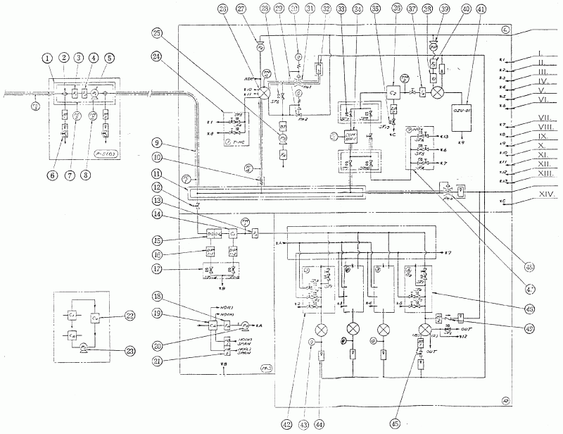
The apparatus first aspirates the sample through the preheated sample tube (pre-sample) into the high temperature chamber, where it is passed to the sample transport pump after two filters. From here the sample is transferred to the measuring system via a heated sample pipe. Here, also from the heated sample distribution line, the sample passes in four directions: to the cooling heat exchanger of the NDIR analysers, to the H FID analyser via a heated capillary, and to the NO/NOx converter selector valves in the direction of the H CLD analyser. The excess is discharged in the by-pass branch after the pressure regulator in the flue gas branch.
The H CLD (NO/NOx) branch passes the converter and its selector valves (NO or NOx), after the electric cooler and a filter, the flue gas sample enters the sensor where it reacts with O3from the ozone generator. After the sensor, the vacuum pump delivers the sample to the collecting flue gas path. The control rotameter is installed in the by-pass path.
In the H FID (THC) branch, the sample passes through a further heated sampling line to the sensor, from where it leaves after a pressure regulator and the control rotameter to the collecting flue gas path.

1. High temperature chamber, 2. Selector valve, 3. Filter I., 4. Filter II., 5. Sampling pump, 6. Rotameter, 7. Temperature sensor (control), 8. Temperature sensor (data acquisition), 9. Oil and condensate separator, 16. Condensate vessel, 17. Valve unit, 18. Air filter, 19. Purge gas heat exchanger, 20. Purge gas pump, 21. NO calibration gas humidifier, 22. Cooling unit, 23. Water circulating pump, 24. Valve assembly, 25. Air control pump, 26. Analyser, 27. Pump, 28. Valve, 29. Pressure regulator, 30. Pressure gauge, 31. Pressure regulator, 32. Rotameter, 33. Valve, 34. NO-NOx converter, 35. Valve, 36. Electric cooler, 37. Filter, 38. ozone decomposer, 39. vacuum pump, 40. filter, 41. ozone generator, 42. valve, 43. pressure gauge, 44. rotameter, 45. buffer tank, 46. valve, 47. valve, 48. pressure regulator, 49. check valve. I. THC Calibration gas, II. CO Calibration gas, III. 0, IV. CO2 Calibration gas, V.0, VI. NOx Calibration gas, VII. zero gas (N2), VIII. zero gas (THC), IX. O2 (for ozone generator), X. level air (THC), XI. H2 (THC), XII. N2, XIII. NO-NOx converter control inlet, XIV. condensate outlet