RENEWABLE FUELS LAB
A MEGÚJULÓ TÜZELŐANYAGOK FELHASZNÁLÁSÁT VIZSGÁLÓ LABORATÓRIUMBAN TALÁLHATÓ BERENDEZÉSEK RÖVID BEMUTATÁSA
Capstone C-30 micro gas turbine
The micro gas turbine unit includes gas turbine, generator, fuel supply control valves, frequency converter unit and control unit. Total unit weight: 405 kg. Gas turbine suitable for natural gas, depot gas, biogas.
1. Structural design of the turbine
The air inlet is a soundproof tube with an air filter inside. Figure 1 shows a cross section of the gas turbine and generator. The generator is a 4-pole permanent magnet 3-phase generator producing high frequency alternating current. The compressor is a small centrifugal design with radial discharge. An internal heat exchanger is integrated in the gas turbine to increase efficiency. Three dual-function fuel nozzles extend into the annular reversing chamber combustion chamber, the 'pilot' nozzles feed the gas directly into the combustion chamber, while the 'premix' nozzles feed the fuel after premixing the gas with air. For clean CH4 gas up to a power limit of 22 kW, 'pilot' nozzles are used, for higher power outputs 'premix' nozzles are used. The compressor and generator are mounted on the same shaft with the axial discharge centripetal turbine. Shaft support is provided by air bearings to allow high speeds and ease of operation.
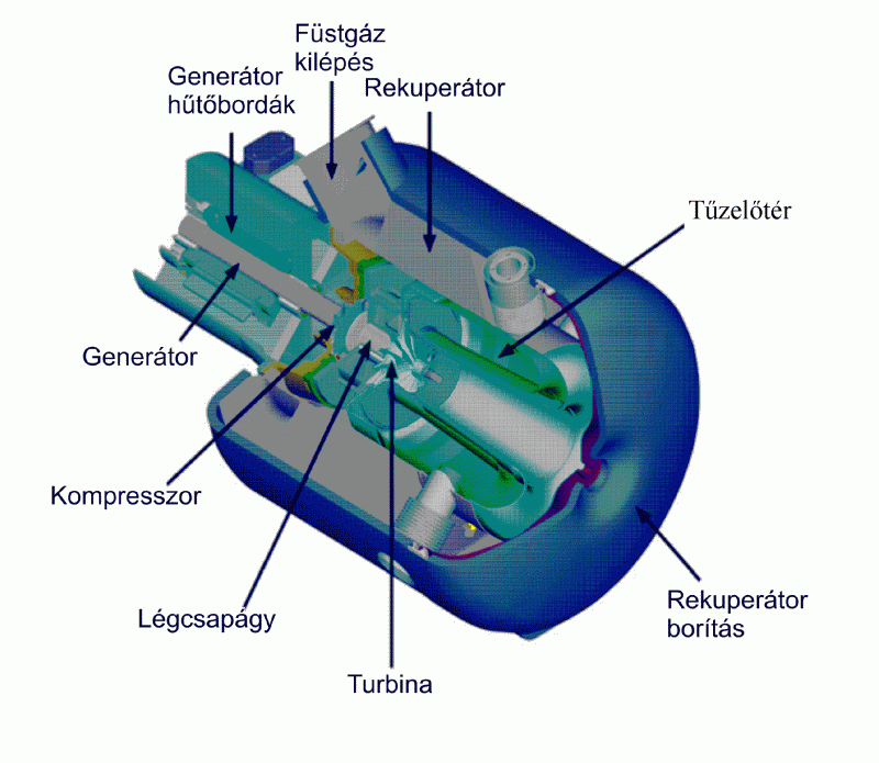
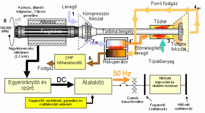
2. Operational diagram
Figures 1 and 2 show the operation of the turbine [2]. The air is intake by the compressor through the generator, thus providing cooling. To increase efficiency, the high pressure air (2) exiting the centrifugal compressor flows through the flue gas/air recuperator, which heats it (4'). The fuel flowing in through the nozzles mixes with the air in the combustion chamber and then burns (3). The hot combustion product expands in the centripetal turbine (4). At the end of the expansion, the flue gas flowing through the recuperator is still at ~275 ºC, making it ideal for combined hot water production. Therefore, a water/flue gas heat exchanger can be placed in the path of the outgoing flue gas. The turbine driven during the hot flue gas expansion is located on a common shaft with the compressor and the generator so that they rotate at the same speed. The high speed of the generator produces high frequency alternating current. In the frequency converter, the alternating current of 2-3 kHz is first converted into direct current and filtered, and then this direct current is used to produce the alternating current of 50 Hz corresponding to the mains frequency.
3. Regulation system
The micro gas turbine can operate in both stand-alone and grid-connected mode. It communicates with the turbine control unit via a serial line via user software on a PC. It can register and process 110 operating parameters and save them to a file. It can display 8 parameters continuously changing on the screen. The control program can run predefined load cycles according to the preset time ranges. Its integration into the power system is facilitated by the possibility to communicate with the load balancer via telephone and internet line, allowing remote start-up and intervention in the turbine operation.
Main parameters for the micro gas turbine:
Nominal electrical power of the gas turbine 30 kW (+0/-2).
RPM at rated power 96,000 rpm.
Efficiency in relation to electrical power 26% (±2).
Specific heat consumption 13.800 kJ/kWh.
Flue gas outlet temperature 275 ºC.
Flue gas mass flow 0,31 kg/s.
Fuel input energy (for methane) 457,000 kJ/h.
Flue gas exit energy 327.000 kJ/h.
Octane Rating Engine
A BME Energetikai Gépek és Rendszerek Tanszék Jendrassik György Hőtechnikai Laboratóriumában megtalálható egy úgynevezett oktánszám mérőmotor is.
The engine is made by the BASF (Badische Anilin- und Soda Fabrik) in 1964 and on him performable to the octane number measurement of the gasolines according to a standard necessary examinations. We compare the knock intensity of the petrol to be examined at constant compression ratio with the similar value of two pieces of reference fuels, beside different air-ratios.
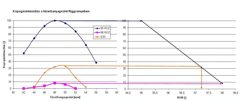
A mérés kiértékelés módszere
The equipment consists of two capital parts: the internal combustion engine and the electric unit which consist of the retarding synchronous engine and the measurement unit electronics equipments.
Single standing, single-cylinder four-stroke, water-cooled Otto Engine with 332 cm3 piston displacements is the engine. For the reproducible of the measurements the engine must be operated on a constant temperature, which is ensured by a cooling unit consist of two parts: the primer circle is filled with distilled water the medium is boiling in the course of the normal operation, the secondary side of the heat exchanger is joined onto the water system.
The electric motor is used for Otto Engine's launch, the function restrains it on his row then, keeps the rev on the rev requested by the measurement procedure. The two units are with a fan belt in a compulsion contact through the flywheel of the petrol engine.
To the transaction of the octane number measurement we have to keep certain function parameters on particular values, Otto Engine's special parts help in these.
First and most important from among these, that let us be allowed to change the compression ratio in the course of the measurement. The special forming of the unit including the cylinder and a cylinder head is necessary to this in order for us to be allowed to change the compression volume beside the constant stroke of the piston. On the exterior surface of the cylinder being mover procession is connected with a snail, in this manner we can lift or raise the cylinder moving on the forced path turning the snail by a hand twins. Through all these the compression ratio (ε) can be optionally chosen between values of 4-11 and the set value is displayed on an indicator disc found on the side of the engine.
The integral part of the engine is a special mix derivational suffix unit. This consists of three combustible containers, these contains the petrol to be measured and the reference fuels with lower and higher octane number than the petrol. The air ratio can be changed by this on a specific manner. The fuels come from the containers into a swimmer house through a bore. It is possible to set a constant liquid level because the swimmer close the bore, and the current level is traceable on a mm arrengement scale on the side of the swimmer house. The engine sucks in a constant volume of air beside all these, the mix comes into existence in a pulveriser. The fuel which the engine being operated can be changed by a three-way valve. Reasonable, that higher liquid level in the swimmer house effects a higher hydrostatics pressure awakes at the jet, and the emergent fuel-air mix will be richer. Though this true reversely, a lower liquid level yields a poorer mix.
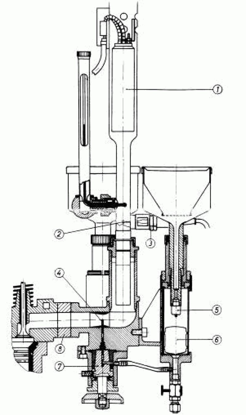
We have to be kept on a defined value of the temperature of the intake air. Onto this aim the mix derivational suffix unit serves, where the air is heated by an electric heater switched by a thermostat to keep the required temperature on a value of 52 °C .
To the examination of the knocking combustion an electronis knockmetring instrument is needed. The instrument consists of a magnetostrictive pick-up mounted on the head of the testing engine, the amplifier and the knockmetring unit.
The magnetostrictive pick-up is actually an inductive transmitter connected to a membrane. The function of the inductive signaller is based on the the law of magnetoelasticity. A magnetized iron rod modifies his magnetic permeability due to the pressure thus the value of the magnetic flux. In the coil around the rod a current proportional to the flux is generated. Because the fluctuation of the flux is proportional to the temporal change of the pressure reigning in the cylinder space, the signal is equal to the knock intensity.
The components originating from the normal combustion are detached from the signal by the electronics. The typical signal of the knocking goes thru an amplifier and rectifier in the second stage and displayed on a scale without a dimension running from 0 to 100 as knock intensity.
The octane number of the examined petrol is determianted from the the received values of the references with known octane number by lineal interpolation.
As the result of the labouratory developments in idicational system is built up on the equipment. In this manner feasible is in the course of Otto Engine's operating the uptake of the indicator diagrams, and different knocking define numbers can be determined and compared by a software.
We supplied the engine in the course of additional developments with exhaust-gas sampling holes, in this manner the NOx,x, CO, CO2 and THC emission depending on the air ratio of the different fuels is easily measurable.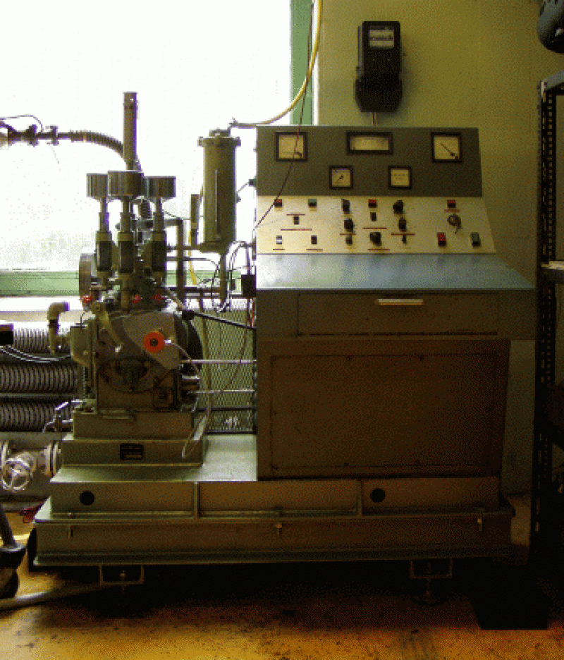
CFR Cetane Rating Engine
A CFR Cetánszám mérőmotor egy egyhengeres, négyütemű, Diesel-körfolyamatú belsőégésű motor. A teljes berendezés „ASTM-CFR” motorként ismeretes, amelyet az Amerikai Anyag- és Mérésügyi Testület (ASTM), valamint az Tüzelőanyag Kutató Testület (CFR) fejlesztett és elismer MSZ EN ISO 5165:1999. A CFR F-5-ös a diesel tüzelőanyagok cetánszámát meghatározó eljáráshoz kifejlesztett berendezés egy egyhengeres, négyütemű, Diesel-körfolyamatú belsőégésű motor. A motor kialakításánál elsődleges szempont, hogy a Diesel-gázolaj minták gyulladási tulajdonságait laboratóriumi körülmények között lehessen vizsgálni. A berendezés különlegessége a hengerfejben kialakított előkamrás égéstér, amely térfogatát (ezáltal a motor kompresszió-viszonyát) változtatni lehet akár a motor üzeme közben is. A berendezés alapjaként a CFR-48D gyári kódú platformrendszer áll. Ez magában foglalja a berendezés belső hajtásrendszerét és a Diesel motorhoz ékszíjjakkal kapcsolt speciális indító, fékező (energia felvevő) háromfázisú aszinkronmotort is. Az aszinkronmotor azon túl, hogy a belsőégésű motor által leadott teljesítményt fölveszi, képes annak fordulatszámát állandó, a szabvány által meghatározott értéken tartani. Az előkamrás vizsgálómotor felépítése Az előkamra és a hengertér (másodlagos égéstér, vagy fő égéstér) között egy furat (úgynevezett előkamra furat) biztosít kapcsolatot. A befecskendező fúvóka tüzelőanyagot porlaszt az előkamrába, melyet az ellentétes oldalról a kézikerékkel állítható dugattyú-rendszer határol. A dugattyú ki és be mozgatható az előkamra-furatban, amellyel üzem közben is lehet a kompresszióviszonyt állítani. A befecskendezés időpontját a befecskendező szivattyún található kézikerékkel változtatjuk meg, amely pontosan beállíthatóvá teszi a befecskendezés kezdetét. A berendezés számításainak alapjául az égésből származó nyomásváltozás (dp/dt) jeladó, a befecskendező tűelmozdulás jeladó és a főtengely szögelfordulását érzékelő referencia jeladók szolgálnak. A mérés során a gyulladási idő pillanatnyi értéke főtengelyfokban leolvasható a berendezés gyulladási idő kijelzőjéről (Ignition Delay). Az égési folyamat vizsgálatára egy piezo jeladóval egészítettük ki a rendszert.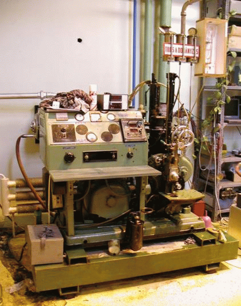 M7-2. ábra Előkamrás motor CFR-F5 égéstere
Cetánszám meghatározása
Habár a pontos összefüggés a cetánszám skála és a motorok jellemzői között egyelőre nem ismeretes, jó néhány összefüggés kimutatható, többek között a motorok hidegindíthatóságában, a gyulladás intenzitásában és az égés kimaradásában. A mérési elv meghatározza a dízel olajok osztályozhatóságát egy – tapasztalati megfontolásból – 0-100-ig osztott ún. cetánszám skálán.
A gyulladási idő és az előbefecskendezési idő együttes beállítással határozzák meg a befecskendezés kezdetétől a gyulladás kezdetéig eltelt időt.
A motor meghatározott, állandó üzemi körülmények között üzemel (hőmérsékletek, fordulatszám). Így három változó paraméter határozza meg az tüzelőanyag égési tulajdonságait (kompresszió, gyulladási idő, befecskendezés kezdete). A berendezés digitális mérőegysége a felső holtponthoz képest mutatja a gyulladási időt és a befecskendezés kezdetét.
A minta cetánszámának megállapításakor két referencia-tüzelőanyag által meghatározott kompresszió állító kézikerék állást hasonlítunk össze a mintánál mért kézikerék-állásához. A mérendő tüzelőanyag eltüzelésekor a kézikerék állás leolvasásával, majd lineáris interpolációval állapítjuk meg a cetánszámát.
M7-2. ábra Előkamrás motor CFR-F5 égéstere
Cetánszám meghatározása
Habár a pontos összefüggés a cetánszám skála és a motorok jellemzői között egyelőre nem ismeretes, jó néhány összefüggés kimutatható, többek között a motorok hidegindíthatóságában, a gyulladás intenzitásában és az égés kimaradásában. A mérési elv meghatározza a dízel olajok osztályozhatóságát egy – tapasztalati megfontolásból – 0-100-ig osztott ún. cetánszám skálán.
A gyulladási idő és az előbefecskendezési idő együttes beállítással határozzák meg a befecskendezés kezdetétől a gyulladás kezdetéig eltelt időt.
A motor meghatározott, állandó üzemi körülmények között üzemel (hőmérsékletek, fordulatszám). Így három változó paraméter határozza meg az tüzelőanyag égési tulajdonságait (kompresszió, gyulladási idő, befecskendezés kezdete). A berendezés digitális mérőegysége a felső holtponthoz képest mutatja a gyulladási időt és a befecskendezés kezdetét.
A minta cetánszámának megállapításakor két referencia-tüzelőanyag által meghatározott kompresszió állító kézikerék állást hasonlítunk össze a mintánál mért kézikerék-állásához. A mérendő tüzelőanyag eltüzelésekor a kézikerék állás leolvasásával, majd lineáris interpolációval állapítjuk meg a cetánszámát.Experimental Gas Engine Unit:
The basis of the gas engine unit is a BAG-20 genset made by "GANZSET" to our order. It is made up of the following units:
- Generator,
- Engine,
- Control cabinet
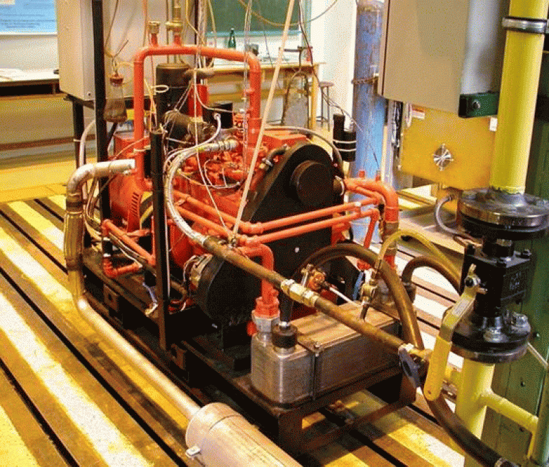
1. The gas engine
Main technical data of the WISCON TOTAL TM27 gas engine:
- Power: 24.6 kW,
- Speed: 1500 rpm,
- Cylinders, number-placement: 4L,
- Cylinder diameter x stroke: 91 mm x 103.2 mm,
- Cylinder capacity: 2.68 litres,
- Dry weight: 253 kg,
- Gas pressure before pressure reducer 1-2 bar,
- Gas pressure after pressure reducer 25-50 mbar,
- Fuel consumption: 82 kW,
- Oil consumption max.: 0.05 litres/hour,
- Coolant volume (engine): 3.6 litres,
- Coolant volume (engine + cooler): approx. 12 litres,
- Max. coolant temperature: 100 °C,
- Engine oil type: MIL-L-2104E,
- Engine oil requirement: 6,7 litres,
- Max. engine oil temperature: 120 °C,
- Minimum oil pressure: 0.5 bar,
- Maximum oil pressure: 2.8-4.1 bar,
- Elektromos rendszer feszültsége 12 V
- Akkumulátor teljesítmény (min) 110 Ah
- Standards BS 5514, ISO 3046.
2. Generator
Main technical data of the asynchronous generator MARELLI CX IM B3 180M:
- Power: 26.4 kW
- Speed: 1500 rpm
- Number of poles: 4
- Voltage: 400 V
- Frequency: 50 Hz
- Insulation class: "H"
- Protection class: IP21
- Standard IEC 34.1, VDE 0530
3. Control cabinet
4. The laboratory gas engine measurement system established:
There are two options for starting the gas engine: starter motor or frequency inverter mode.
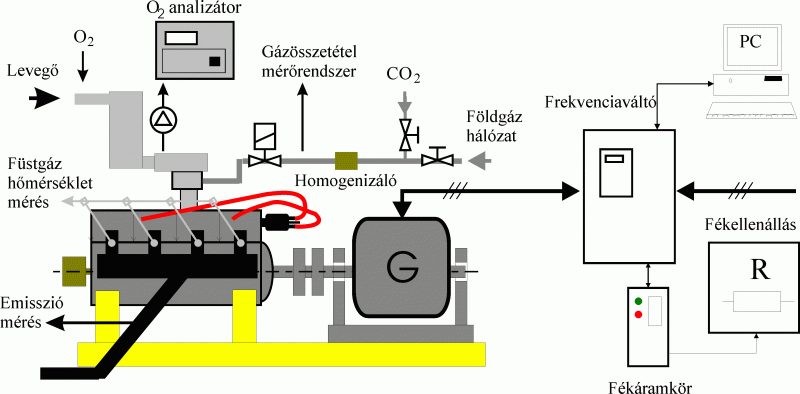
1.figure. The gas engine measuring system.

2. figure. Cooling system of the gas engine and measuring points
A measuring point for the exhaust gas composition was installed in the common exhaust manifold. The exhaust system was connected to the chimney available in the laboratory.
THE AUDI ENGINE TEST STATION
The AUDI engine test system arrived at the Department's laboratory on 21 December 2004.
The first engine tested, used mainly for educational purposes, was a 3.0 l TDI engine
In today's modern test cycles, not only the braking of the internal combustion engine but also the external propulsion is required, allowing e.g. the simulation of the engine braking operation of vehicles. This is the reason for the major upgrading of the brake bench in 2022
The advantage of externally driving the tested motors from the brake is the ability to test the regenerative range of the electric motors used in today's electric transport vehicles. However, in order to provide external propulsion, it is not sufficient to use passive braking devices, an active machine must also be used in the system. Thus, the modified system incorporates an asynchronous machine and an eddy current braking machine, which together act as the torque generating system.
The eddy-current brake machine installed in the new brake bench measuring station is a Borghi & Saveri FE350-S, capable of absorbing a maximum shaft power of 260 𝑘𝑊 maximum power asynchronous drive. The hybrid system, thanks to the two torque generation devices, allows a maximum output of 60 𝑘𝑊 csúcsteljesítményű tagja. A hibrid rendszer a két nyomatékképző berendezésnek köszönhetően maximálisan 60 𝑘𝑊 shaft power and 320 𝑘𝑊 brake power to be applied with a proprietary measurement control and regulation system.
Dual fuel AIFO 8031 diesel genset
In a dual-fuel system, the liquid primary fuel is introduced into the intake air stream by atomization or vaporization, thus introducing a homogeneous fuel-air mixture of a certain concentration into the cylinder. This mixture is ignited by the flame of the injected diesel. This necessitates the installation of separate fuel lines, tanks, regulators and atomizers. But not only liquid fuel but also gas fuel can be used. The proportion of primary fuel should and can be varied according to the load.
The equipment implemented is based on a GanzAir TAD33 diesel generator set. It is composed of three main units, such as AIFO 8031 i06.05 diesel engine, generator and switchgear cabinet. In line with the state-of-the-art design, the equipment is equipped with a generator with one bearing, where the other bearing is the main shaft bearing of the engine.
Main technical specifications of the AIFO 8031 i06.05 engine
Power: 32 kW
Speed: 1500 rpm
Cylinders, number-placement: 3L
Valve control: OHV, 6 valves
Cylinder diameter x stroke: 104 mm x 115 mm
Cylinder capacity: 2.9 litres
Compression ratio: 17:1
To install the primary fuel injection system on the engine, a new intake manifold had to be made. The intake manifold was welded from stainless steel patent elbows and machined pieces to accommodate the nozzles. The system was designed in such a way that the fuel was sprayed onto the intake valves by the nozzles, with as little contact as possible with the walls of the intake manifold to avoid condensation.
In the experimental dual-fuel system, it is possible to index one cylinder and measure the pressure of the ignition diesel line of the same cylinder. The system can also be used with gaseous fuels (e.g. LPG, natural gas and natural gas-hydrogen mixtures).
1. Figure: Dual fuel AIFO 8031 diesel genset